RF Test Oscillator
A test oscillator project for testing AM broadcast receivers. It generates a 1 kHz tone modulated onto a 535 kHz and 455 kHz carrier, which can be used to test the sensitivity and selectivity of AM radios.
Project Details
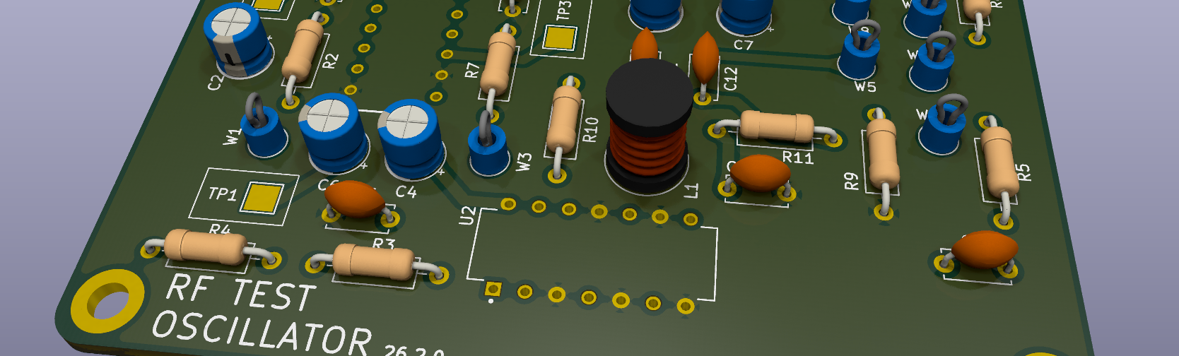
The RF Test Oscillator is designed to provide a stable and consistent signal for testing AM broadcast receivers. It uses a combination of analog and digital components to generate the desired frequencies and modulation. The project includes a custom PCB design, which can be fabricated using standard PCB manufacturing services.
Let's take a look at the schematic and the circuit modules used in this project:
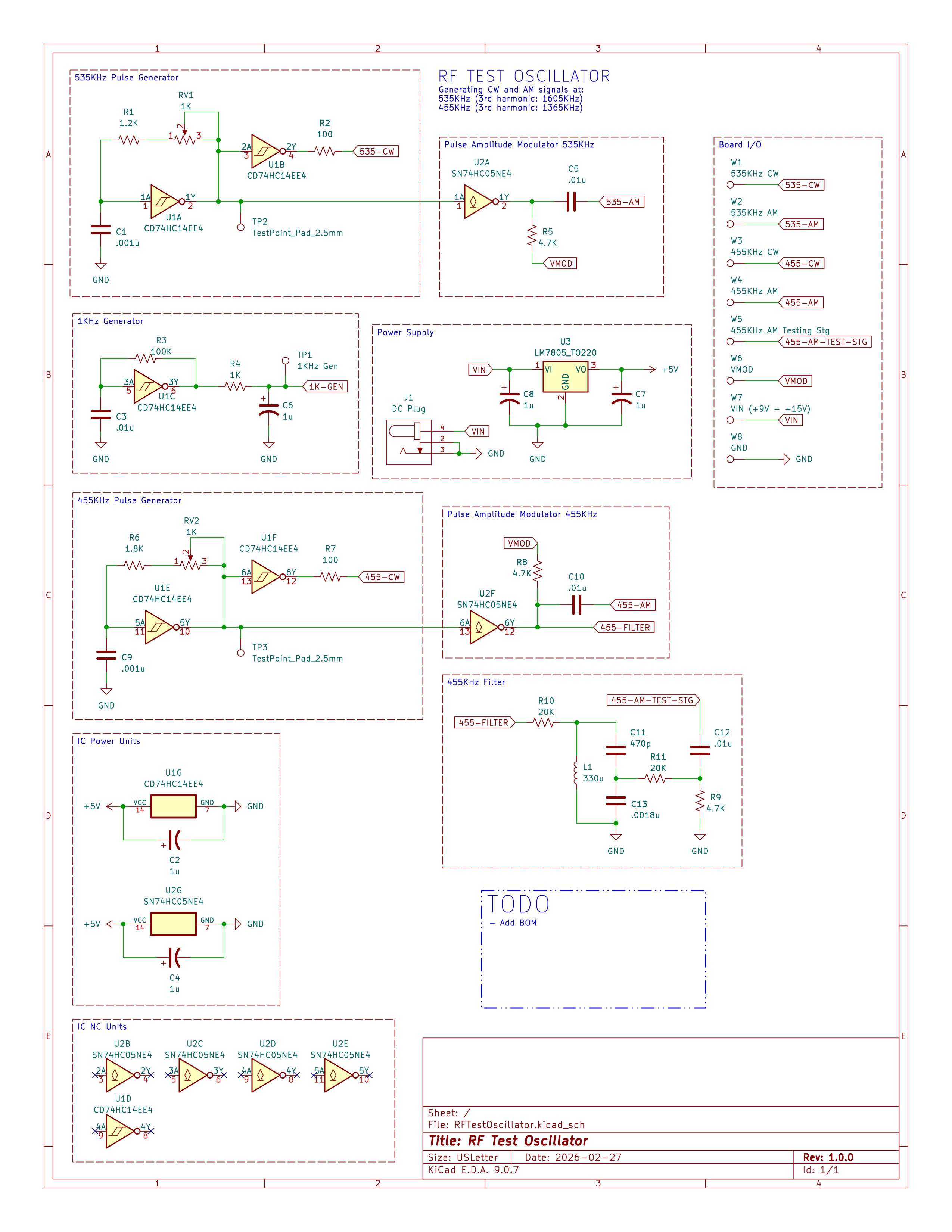
The schematic shows the overall design of the RF Test Oscillator. It includes a Schmitt trigger relaxation oscillator to generate the 535 kHz and 455 kHz carrier frequencies, which are then modulated with a 1 kHz tone using a simple amplitude modulation circuit. The square wave output has the advantage of providing 3rd order harmonics that can be used to test the selectivity of AM radios at different frequencies.
The circuit is powered by a 9V - 12V DC input to a regulated 5V supply, and the output can be taken from the modulation stage for each fundimental frequency to provide the desired test signal. Output signals are available for both the 535 kHz and 455 kHz carriers as well as the modulated signals. Test jacks are provided for easy connection to test equipment.
Circuit Modules
-
535 kHz/455 kHz Carrier Generators
These modules generate the 535 kHz and 455 kHz carrier frequencies using a Schmitt trigger inverter in a hysteretic configuration. The frequency is determined by the RC network connected to the inverter and fine tuned by a potentiometer. This output feed to the modulation stage. It is also buffered via another Schmitt trigger inverter to provide the carrier signal.
-
1 kHz Modulator
This module generates a 1 kHz tone using another Schmitt trigger inverter in a similar configuration to the carrier generators. The output is then fed into the modulation stage.
-
Amplitude Modulator
The amplitude modulation is achived by connecting the output of the 1 kHz modulator to a capacitor that feeds a modulation voltage into the carrier signal path. This creates a simple AM signal where the amplitude of the carrier is varied according to the 1 kHz tone.
-
Power Supply
The circuit is powered by a 9V - 12V DC input, which is regulated down to 5V using a standard linear voltage regulator. This provides a stable power supply for the oscillators and modulators.
-
455 kHz Filter
-
Output Stage
The output stage provides test jacks for the carrier and modulated signals. This allows for easy connection to test equipment such as oscilloscopes or AM radios for testing purposes.