Schmitt Trigger Inverter Relaxation Oscillator or How I Learned to Stop Worrying and Love the Square Wave
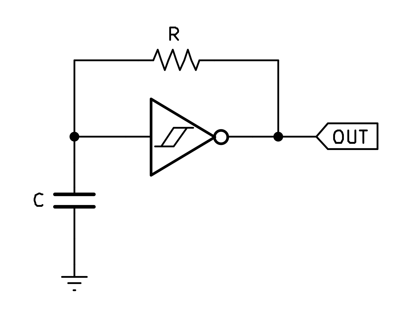
A Schmitt Trigger Inverter Relaxation Oscillator is a type of relaxation oscillator that uses a Schmitt trigger inverter to produce a square wave output. The frequency of oscillation can be approximated by the following formula:
$$f ≈ {1 \over k \cdot R \cdot C}$$Where: \(k\) is a constant depending on the specific device.
- 74HC14 (High-speed CMOS): \(k ≈ 0.8\)
- 74HCT14 (High-speed CMOS with TTL input levels): \(k ≈ 0.67\)
- CD40106 / HEF40106 (Standard CMOS): \(k ≈ 1.2\)
For a more accurate calculation of the frequency, especially when the threshold voltages of the Schmitt trigger are not symmetrical, the following formula can be used:
$$f={1 \over 2RC \; ln \left ( {V_{T+} \over V_{T-}} \right ) }$$Where: \(V_{T+}\) is the upper threshold voltage and \(V_{T-}\) is the lower threshold voltage of the Schmitt trigger. This can be found in the datasheet for each specific device.
By selecting appropriate values for the resistor (R) and capacitor (C), and considering the specific characteristics of the Schmitt trigger inverter being used, you can design a relaxation oscillator that meets your desired frequency requirements.
Let's take a look at a practical example of a Schmitt Trigger Inverter Relaxation Oscillator using a 74HC14:
In this example, we will be looking at the 1 kHz modulation signal generator used in the RF Test Oscillator project. The circuit uses a 74HC14 Schmitt trigger inverter to generate a 1 kHz square wave signal. The frequency is determined by the values of the resistor and capacitor connected to the input of the inverter.
Using the formula \(f ≈ {1 \over k \cdot R \cdot C}\) with \(k ≈ 0.8\) for the 74HC14, we can calculate the frequency using some common values. We need to keep in mind our CMOS Schmitt trigger in this configuration should use at minimum a 1 kΩ - 2 kΩ resistor to avoid excessive current and overdriving.
We'll choose a 100 kΩ resistor and a .01 µF capacitor for our example: $$f ≈ {1 \over 0.8 \cdot 100,000 \cdot 0.00000001}$$ $$f ≈ 1,250 Hz$$
Great! This gives us a frequency of approximately 1.25 kHz, which is close to our target of 1 kHz. Let's get this wired up on the breadboard and see what happens!
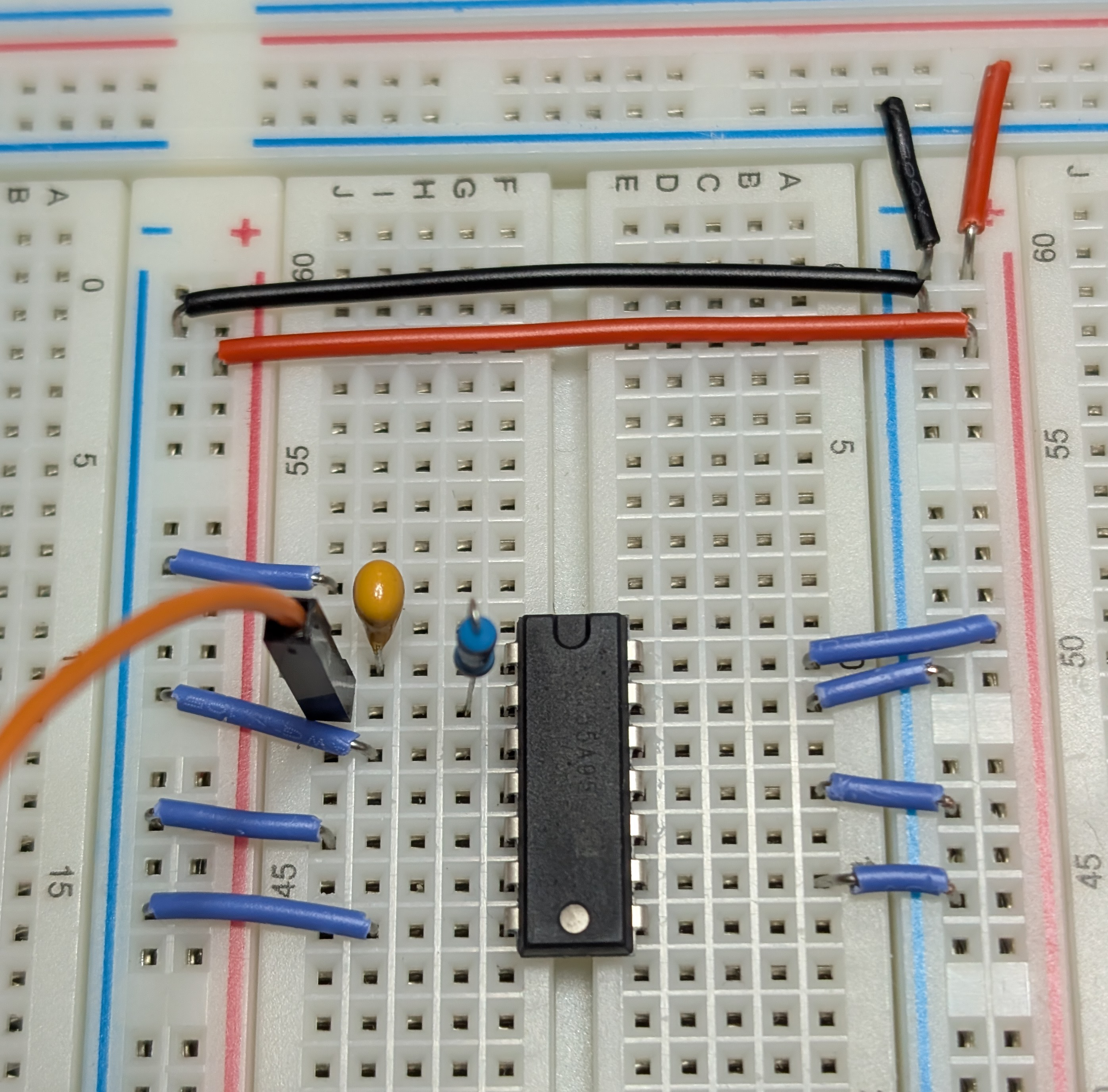
After wiring this up on the breadboard, we can now throw the switch on the trusty power supply and take a look at the output on the oscilloscope. We should see a nice square wave oscillating at around 1.25 kHz, just as we calculated!

Hmm, not quite what we were looking for. Let's take a look at that other formula with the threshold voltages to see if we can get a more accurate prediction of the frequency. According to the datasheet for the CD74HC14 we are using, the upper threshold voltage \(V_{T+}\) and the lower threshold voltage \(V_{T-}\) vary by supply voltage and have minimum and maximum values. The datasheet also provides \(\Delta V_{T}\) values.
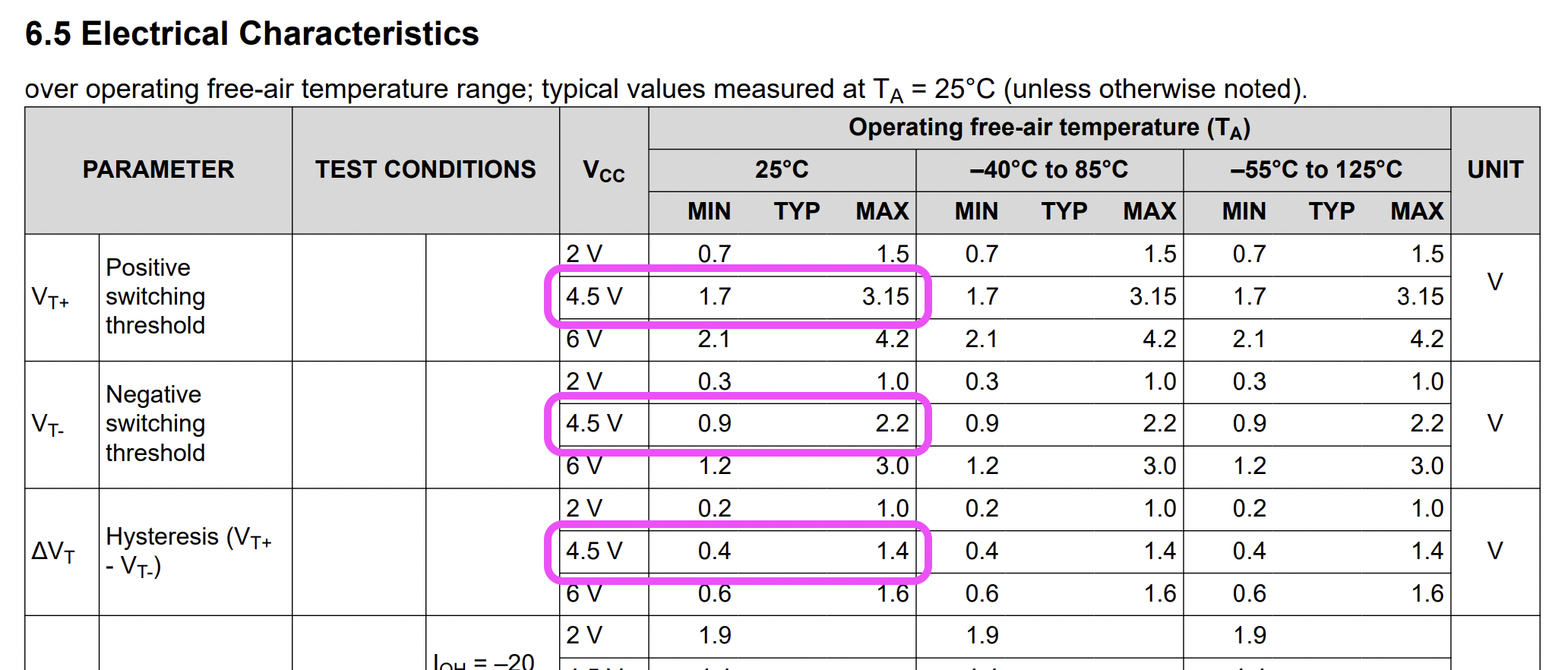
We can see that \(V_{T-}\) can be as low as 0.9V and \(V_{T+}\) can be as high as 3.15V at a supply voltage of 4.5V. That's a 2.25V difference. However, \(\Delta V_{T}\) maximum is 1.4V, which means we'll never have a device with values at both extremes. It would be helpful to have an idea of the possible range of frequencies we could see for this circuit, so let's crunch some numbers with the help of a spreadsheet. We'll be looking at the low and high extremes using both the minimum and maximum \(\Delta V_{T}\) values.
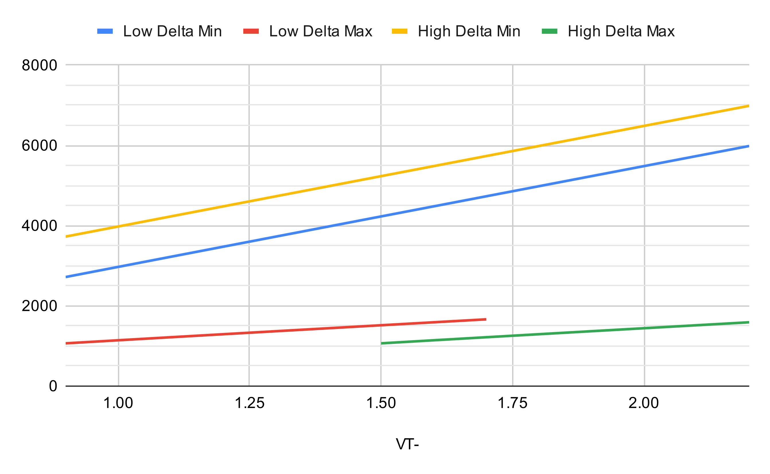
As we can see, the frequency can vary quite a bit based on the specific device and its threshold voltages. In our case, we are seeing a frequency of 1.88 kHz, which is higher than our initial calculation of 1.25 kHz. This could be due to the specific characteristics of the device we are using, as well as any variations in the resistor and capacitor values.
After some experimentation with different resistor and capacitor values, we can find a combination that gets us closer to our target frequency of 1 kHz. For example, using an 82 kΩ resistor and a .022 µF capacitor gives us:

With these values, we are now seeing a frequency of around 1.11 kHz, which is much closer to our target of 1 kHz. For application in the RF Test Oscillator project, this is close enough for our purposes.
In conclusion, the Schmitt Trigger Inverter Relaxation Oscillator is a versatile and easy-to-build circuit that can be used to generate square wave signals at a wide range of frequencies. By understanding the characteristics of the Schmitt trigger inverter and using the appropriate formulas, you can design an oscillator that meets your specific needs.